|
Welcome
to my pneumatics page (no implied affiliation with the Lego
Group). This page contains pictures of my own designs as well as links to works of
others.
 There are currently two popular compressor
designs: small single-pump
compressor by Michael Powell and dual-pump compressor by
Ralph Hempel. I like both designs, especially Ralph's one, but I thought that I can
come up with something better. First, I wanted full-stroke dual-pump version. Second, I
wanted to use new Lego 9V motor geared down compared to Ralph's version to yield higher
pressure. My best result so far is the compressor shown on Fig.1 (see assembly instructions
below).
There are currently two popular compressor
designs: small single-pump
compressor by Michael Powell and dual-pump compressor by
Ralph Hempel. I like both designs, especially Ralph's one, but I thought that I can
come up with something better. First, I wanted full-stroke dual-pump version. Second, I
wanted to use new Lego 9V motor geared down compared to Ralph's version to yield higher
pressure. My best result so far is the compressor shown on Fig.1 (see assembly instructions
below).
 
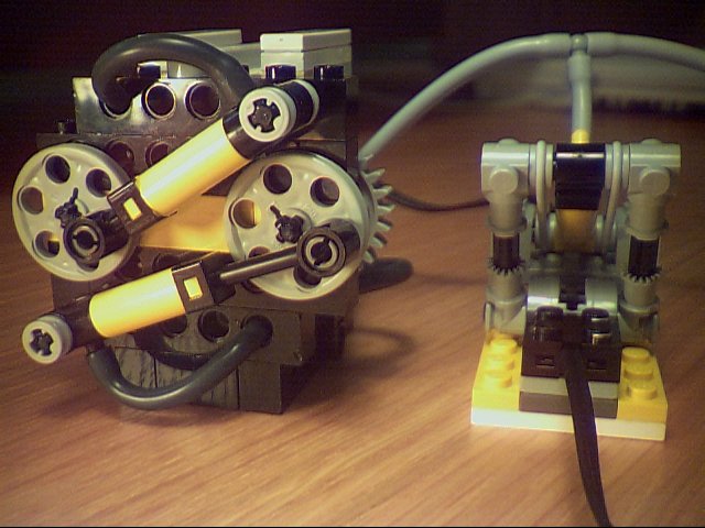
Fig.1 Front and rear views of the compressor
 When I finished the compressor I started thinking
about pressure switches. Two switch designs I found (by Ralph Hempel
and Larry Pieniazek) are nice but a
little bit too large for the simple function they accomplish. My idea was to put the
cylinder on top of the switch and use connection plates as functional elements. First, I
measured forward-off-reverse-off angles of the rotary switch (in case you are
interested, the angles in degrees are -18..18(off), 18..72(forward), 72..108(off), and
108..162(reverse)) and then calculated possible trajectories of the cylinder arm using
lego blueprint and pair of compasses.
When I finished the compressor I started thinking
about pressure switches. Two switch designs I found (by Ralph Hempel
and Larry Pieniazek) are nice but a
little bit too large for the simple function they accomplish. My idea was to put the
cylinder on top of the switch and use connection plates as functional elements. First, I
measured forward-off-reverse-off angles of the rotary switch (in case you are
interested, the angles in degrees are -18..18(off), 18..72(forward), 72..108(off), and
108..162(reverse)) and then calculated possible trajectories of the cylinder arm using
lego blueprint and pair of compasses.
  
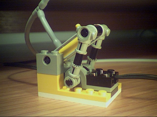
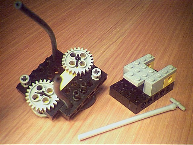
Fig.2 Pressure switch attached to the compressor
 The
pressure switch assembly is straightforward; the only tricky part is to find the correct
angle for the polarity switch axle. When the switch is assembled properly, it cuts off the
power just before the end of the cylinder stroke. The
pressure switch assembly is straightforward; the only tricky part is to find the correct
angle for the polarity switch axle. When the switch is assembled properly, it cuts off the
power just before the end of the cylinder stroke.
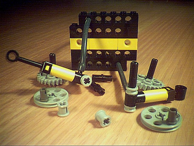
The compressor assembly is more
complicated; the figures below illustrate various stages of the assembly. Note that the
bottom part is attached to the front part on a half-hole offset. The relatively hard to
find two-hole 1x2 beam is not essential to the design; it may be replaced by the
"small turntable" System piece or plain brick of the same size.
 
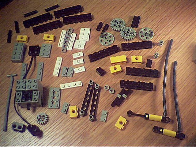
Fig.3 Compressor assembly: required pieces, front part
 
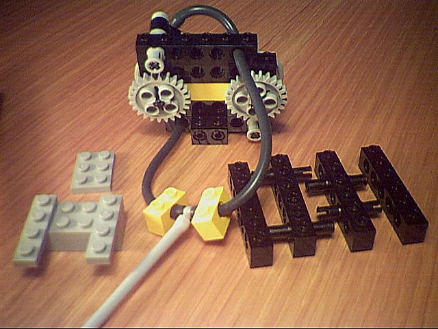
Fig.4 Compressor assembly: bottom part
 
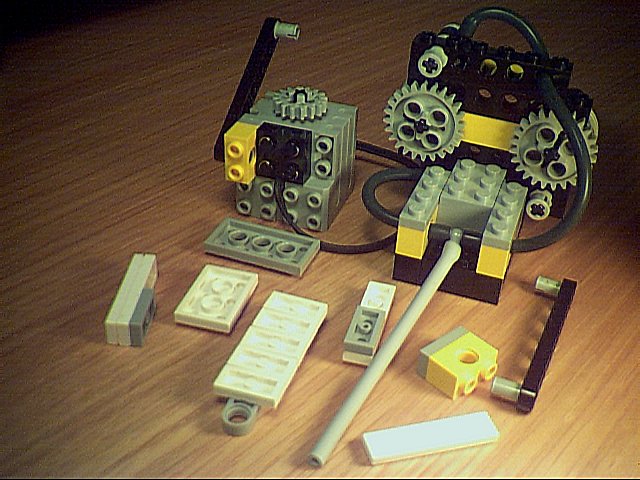
Fig.5 Compressor assembly: motor and top part
If you need more details, check the DAT file (no pumps and tubing).
|